


Design Your Own Triple USB Power Bank from Scratch
In the current digital era, where our dependency on portable electronic gadgets is continually growing, the necessity for reliable electricity on the go has soared substantially. To overcome this, what you need is an easily, and readily accessible device that can recharge your devices on the go, or to be precise, a Power bank. Known also as a portable charger or external battery pack, a power bank allows you to recharge your cell phones, tablets, laptops, and other USB-powered devices whenever and wherever you need to.
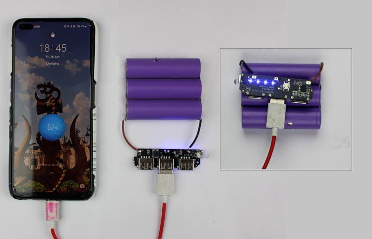
The content of this article will demonstrate how one can build a power bank by implementing a very simplistic circuit schematic.
Components required for Power Bank
The following components will be used for building this power bank.
- 3 x 18650 Lithium Cell
- 1 x Triple USB Power Bank Module
Circuit Diagram for the Power Bank

18650 Lithium Cell

The 18650 Li Cell is an essential part of the circuit as it serves the voltage using which the devices can be charged. It gets its name due to its characteristics, that is, 18 from the 18mm diameter, and 65 from its height being 65mm. These cells are rechargeable and have an output of 3.7V.
The ability to store an immense quantity of energy in a limited space is one of the primary perks of batteries powered by Li-ion. Because of this, they are excellent choices for portable devices where weight and storage capacity are important factors.
Power Bank Module [YN-957-KC]
The 3 USB Power Bank module is a simple solution for charging multiple devices at once, using its 3 USB-A -Output ports. It incorporates a load management module, an LED indicator module along with a protection module. This device is primarily used in most batteries for boosting. Since it has a low static current, the whole circuit only consumes 1mA.
The module operates within a voltage range of 3.7V to 5V. The input voltage is usually around 5V when charging the power bank. The output voltage received from the batteries is around 3.7V, which is boosted to 5V to charge the connected peripheral devices.

- Positive Terminal: The positive terminal of the battery is connected to the positive terminal of the power bank module, to supply power.
- Negative Terminal: The negative terminal of the battery is connected to the negative terminal of the power bank module.
- XB 7608: The XB 7608 is a high-integration solution for battery protection. It contains advanced power MOSFET, high-accuracy voltage detection circuits, and delay circuits. The IC incorporates built-in safeguards to protect against charger reverse connection and battery cell reverse connection, enhancing overall safety during the charging process. It has all the protection functions required in the battery application including overcharging, over-discharging, overcurrent, and load short-circuiting protection etc.

- USB Ports: The Triple USB Power Bank module has a total of four USB ports. Three of these ports are USB-A, which are made to supply peripheral devices with both power and data. Therefore, these ports can be used to charge and connect devices like smartphones and tablets using USB A cables. A USB Type Micro-B port serves as the module's fourth port. This port connects the module to an external power supply to charge the power bank's Li-ion batteries. One may charge their device and/or transfer data using a USB Type Micro-B connector.
- Push Button: The push button present on the module serves as a power button. The user can manually power ON the Power Bank by pressing the button once, and it can be switched OFF by pressing the button twice. If the user holds the push button for a few seconds, the external LED connected to the manual turns on and can be used as a flashlight. When the button is pressed once, a certain number of SMD LEDs will turn ON. Why these LEDs glow up and what they represent are explained in the next section.
- External LED: The 8mm LED on the module can be used as a flashlight if needed. It can be switched on by pressing and holding the push button on the module for a few seconds. The LED's intensity depends on the battery percentage available. The same procedure needs to be followed to turn the LED off.
The picture below shows the LED being used as a flashlight.

-
FM 5324: The highest boost efficiency can reach up to 94% @ 2.4A.
The IC has short circuit, overvoltage, and overcurrent protection as well, which makes it more desirable to be used in power bank applications. The power bank module comprises a booster IC, FM5324, which is used to boost the voltage of the voltage received from the Li-ion batteries (3.7V) to 5V, the required voltage to charge mobile or tablets. One of its primary functions is lithium battery charge management, encompassing trickle charging, constant current charging, and constant voltage charging. This ensures an efficient and controlled charging process for the connected battery. The FM5324 has three LED drive connectors that can drive four LEDs for displaying battery life.

- Functioning of SMD LEDs: The module consists of Four SMD LEDs. These LEDs are used to indicate the remaining battery capacity when external devices are being charged. The LEDs also indicate the percentage of charging when the power bank is being charged through the Micro-USB port.

A more detailed explanation is shared below:
|
LED Display Mode · Bright o Blink while charging × Not Bright |
Output to charge external devices |
•••• |
75% - 100% |
|
•••× |
50% - 75% |
||
|
••×× |
25% - 50% |
||
|
•××× |
0% - 25% |
||
|
×××× |
Discharged |
||
|
The power bank being charged |
o××× |
0% - 25% |
|
|
•o×× |
25% - 50% |
||
|
••o× |
50% - 75% |
||
|
•••o |
75% - 100% |
||
|
•••• |
Fully Charged |
The user can also manually check the battery capacity of the power bank, by pressing the push button once. The number of LEDs glowing represents the percentage of battery remaining (refer above table).
Working of the Power Bank
The overall working of the Power Bank includes several steps such as charging the power bank, voltage boost, output power distribution, and many more. Each of the steps is explained briefly in this section.
- Input Charging: The input charging circuit activates when the power bank module is connected to an outside power source, such as a USB charger or computer. Its internal circuitry regulates the incoming electrical current and voltage to ensure a secure charge of the power bank's internal batteries (Li-ion in this case).

- Storing Energy: One or more rechargeable batteries, often composed of lithium-ion or lithium-polymer, are housed inside the power bank to store electrical energy. The batteries are designed for preserving the electrical charge until it is demanded.
- Voltage Boosting (DC-DC Boost): Li-ion batteries operate at a lower voltage (around 3.7V), so a voltage boost is necessary. This is due to most USB-powered devices operating at 5V or higher. The module includes a DC-DC boost converter (FM 5324) to step up the battery voltage to the desired output voltage. It operates at high efficiency (90-95%) to minimise power loss during the voltage conversion process.
- Power Distribution: The devices which require charging can be easily connected to one of the USB ports available on the power bank using the appropriate USB Cable. To guarantee that the gadget is charged securely and effectively, the power bank's circuitry regulates the flow of current from its internal batteries to the target device.
- Charging and LED Indicators: Once a device is connected to one of the USB ports, the power bank starts delivering the stored electrical energy into the device’s battery, just like a regular charger. While charging any external device, the SMD LEDs are turned ON. The remaining battery capacity is indicated by these LEDs.
- Recharging the Power Bank: Once the devices are charged, one can easily recharge the power bank by implementing the first step of this section. Simply connect the power bank to an external power source to recharge the batteries present inside the power bank. The voltage is carefully regulated by the module, so that the maximum voltage that reaches the batteries, is never higher than 4.2V.
Conclusion
In conclusion, the YN-957 is a remarkable module that allows the user to charge up to three devices simultaneously. The working of the module is simplistic and its implementation is easy to understand.
The power bank designed in this article can easily be enhanced by adding more batteries, to provide better storage. However, increasing the number of batteries would mean that the time required for the power bank to get fully charged also increases.