


Build Laser Security System using LDR Sensor and BC547
If you want to make your surroundings safer then it comes to security. What if you can protect your house or garage or any important belongings with the help of a laser system. Whenever the laser got interrupted, it will sound an alarm to make you alert that someone has invaded.
So, In this tutorial, we are going to learn how to make a laser security system just with the help of a transistor and a few basic components. Let’s make it!
BC547 Pinout

BJT Datasheet
|
Model No. |
BC 547 |
|
DC Current Gain (hFE) |
Min: 110 Max:800 |
|
Collector Current (IC) |
100 mA |
|
Collector Power Dissipation |
500 mW |
|
Collector-Base Voltage (VCBO) |
Max: 50V |
|
Collector-Emitter Voltage (VCEO) |
Max: 45V |
|
Emitter-Base Voltage (VEBO) |
Max: 6V |
|
Junction Temperature |
150 °C |
|
Storage Temperature |
-65 ~ 150 °C |
What is LDR?

LDR stands for Light Dependent Resistor. LDRs are tiny light-sensing device which is also known as Photoresistors. It has two terminals. LDR is a resistor whose resistance varies as the amount of light falling on it varies. The resistance of these LDR decreases with an increase in intensity of light and vice-versa. This property allows us to use them for making light sensing circuits and many other applications.
For using an LDR, we always have to make a voltage divider circuit and same we are using in this project. When the value of resistance of LDR changes in comparison to the fixed resistance, the voltage across it also changes and this helps in triggering our transistor for our project.
What is a laser diode?

The LASER in Laser Diode stands for “Light Amplification by Stimulated Emission of Radiation”. It is also referred as a semiconductor laser. Its main feature is to emit light with the same phase and wavelength.
Laser oscillation is achieved by amplifying light generated through current injection between two mirrors in laser. A laser diode is an LED that amplifies and emits light using reflectors which is pointed type in nature. Semiconductors materials such as InGaAIP, AlGaAs, InGaN, and ZnO, etc are typically adopted as the element material in making of them.
Components required
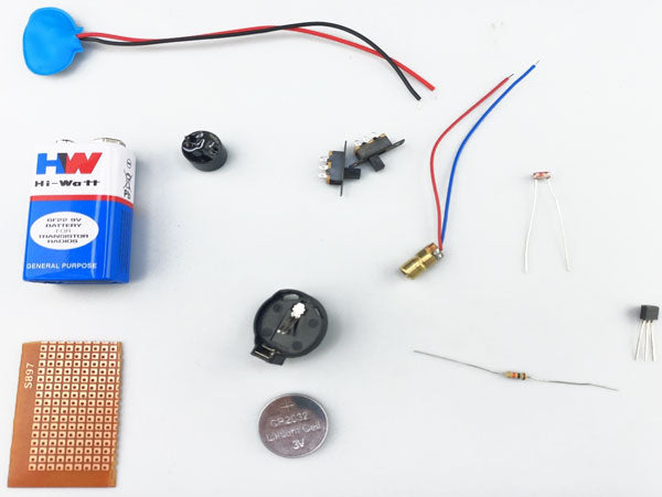
- BC547 NPN Transistor
- LDR Sensor
- Laser Diode
- Resistor (10K)
- Active buzzer
- 3V Coin Cell Battery Holder
- Micro Lithium Coin Cell 3
- DPDT Miniature Slide Switch
- 9V battery
- 9V battery connector
- Perf Board
- Soldering iron
- Solder wire
Laser Security System Circuit Diagram

In the above circuit diagram, we can see that the NPN transistor is acting as a switch whose base is connected to the 10K resistor and one terminal of LDR. A 9volt power supply is given to the collector of the transistor. The buzzer is connected to the emitter terminal of the transistor. The emitter terminal and another terminal of LDR are connected to the ground with the help of an ON-OFF switch.
The laser setup has a simple 3volt coin cell to power the laser and an ON-OFF switch is connected to it.
Laser Security System Working
The working of the circuit is simply based on a voltage divider circuit. As the light intensity on LDR increases its resistance decreases, so when laser light is falling on LDR, its resistance goes very low hence the 9volt supply gets connected to the ground with the help of a 10K resistor, and in this way base of the transistor receives low value or in other words transistor is OFF.
Now as soon as light intensity decreases or it laser gets interrupted by someone, LDR resistance increases which in turn gives a high value to the base of the transistor, and hence transistor turns on, and finally, the buzzer sounds up. In this way, our project is working and providing us with a security system using a laser.
Final Project looks like this.

Troubleshooting
Circuit not working?You must check all the connections as per the circuit diagram. A proper rating of components is a must. Cross-check the soldering joints if you have missed anything to solder.
Laser diode not working?Ensure that the laser diode is in working condition. If its intensity is low try to replace the coin cell. Do not hit the laser into your eyes.
LDR is not responding?Ensure that LDR is in working condition. Take a multimeter and check the resistance of LDR by varying the light intensity on it. If its value is changing that means LDR is working fine.
Is BJT not working?You must take an NPN transistor for the fine operation of the circuit. Another type of transistor will not work here.