


How to Interface TSOP38238 IR Receiver with Arduino
The TSOP38238 is a generic infrared (IR) receiver diode commonly use inside IR remotes to capture the IR signals and decode them into digital signals. This receiver diode is capable of capturing IR signals sent by remotes operating at a frequency of 38kHz. Many commonly used remotes in India, such as those for TVs and air conditioners (ACs), work at this frequency. The diode uses very low energy due to its design and is capable to filter out unwanted signals from sources like incandescent, halogen, fluorescent lights, and sunlight, ensuring reliable signal reception.
TSOP38238 IR Receiver Specifications
- Supply Voltage Range: 2.5 V to 5.5 V
- Required Low Power to operate about 3mA current.
- Package supports Carrier Frequency 38KHz.
- Photodetector, Internal Filter, and preamplifier are included in a single package.
- Output voltage is -0.3 to (VS + 0.3) V.
- Output current is 5 mA.
TSOP38238 Pinout

The sensor comes with three pins for interfacing with the microcontroller boards which include:
- Vs: Terminal used to provide external power supply pin whose range is 5 V to 5.5 V.
- GND: It is the center pin that is connected to the ground.
- OUT: Pin used to output the decoded signal which should be connected to a microcontroller.
Circuit Design for Interfacing TSOP38238 IR Receiver with Arduino
In this project, we will control LEDs using IR Remote by using the combination of the IR receiver and Arduino. Also, we will learn about decoding the IR remote codes.
Components Required
- TSOP38238 IR Receiver Diode (38kHz)
- Arduino Uno R3
- Small LEDs for five colors (Red, Green, Blue, White, Yellow)
- IR Remote
Circuit Diagram for Interfacing TSOP38238 IR Receiver with Arduino
For the circuit design, we will use Tinkercad Software. In previous article, we learned How to use TinkerCad to create circuit with Arduino.

IR receiver module connection:
- Connect the VCC pin to 5V on the Arduino.
- Connect the GND pin to GND on the Arduino.
- Connect the OUT pin to a digital pin (e.g., 11) on the Arduino.
LEDs connection:
- Connect all ground terminals of LEDs to the ground of the Arduino.
- Connect the +ve terminal of each LED to a digital pin (e.g., 9, 10, 13) on the Arduino through appropriate current-limiting resistors which are optional.

Arduino Code for Interfacing TSOP38238 IR Receiver with Arduino
To control LEDs using an IR remote, firstly we need to decode the required buttons on the remote. The Below code will show you the required button Hex codes on the Serial Monitor when you press each button on the remote. Note all the codes, we will be using in the next program.
To successfully run the code, you need to install the IRremote library which you will find under the library manager of IDE.
The below Image of the Serial monitor shows the codes of each particular button on the IR Remote.

Now the below code operates the functioning of the LEDs using the remote buttons including turning ON and Off.
The +ve pin of each Led is connected to the different digital pins of the Arduino. If you are using different pins, change the PIN Inside the code also.
Inside Switch Case, there will be a different Hex code, you have to replace them with your previously noted Hex codes.
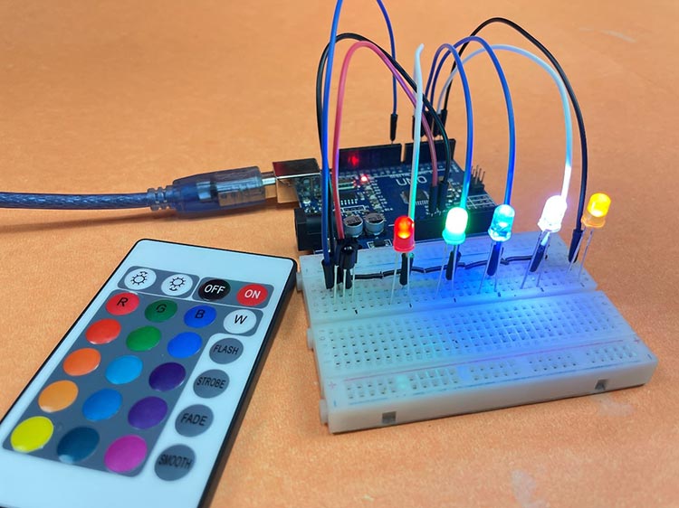
Demonstration of Controlling LEDs using IR Remote
After Successfully uploading the code, press the same buttons on the remote to glow the LEDs. Similarly, using the same button you can turn off them also.
Hope you liked and enjoyed the project and learned something useful from it. If you have any questions, you can leave them in the comment section below.