


Interfacing Ultrasonic Sensor HC-SR04 with Arduino
The Ultrasonic Sensor Module works by using sound waves to figure out how far an object is. The module uses two transducers: one transmits out a high-pitched sound, and the other receives the sound signal bouncing back from the object. These sensors are cheap, easy to use, and don't need much power to operate. They can even be used to measure how deep water is because sound travels through water. The range of measuring distance is from about 2cm to 400cm.
HC-SR04 Specifications
- Operating voltage: +5V
- Operating Current: <15mA
- Working Frequency: 40Hz
- Measuring Angle: 15 degrees
- Accuracy: 3mm
The basic working principles:
- Trigger pin should have a High-level signal lasting 10us.
- Transmitter emits eight 40 kHz frequency signals. The echo pin goes high when the signal is sent and drops low when it's received.
- Receiver receives the reflected signal; the high-level duration of the echo pin represents the time from sending to receiving the ultrasonic pulse.
Hence, the distance of object is = (time duration x speed of sound (340 m/s)) / 2
Ultrasonic Sensor HC-SR04 Pinout & Parts Description
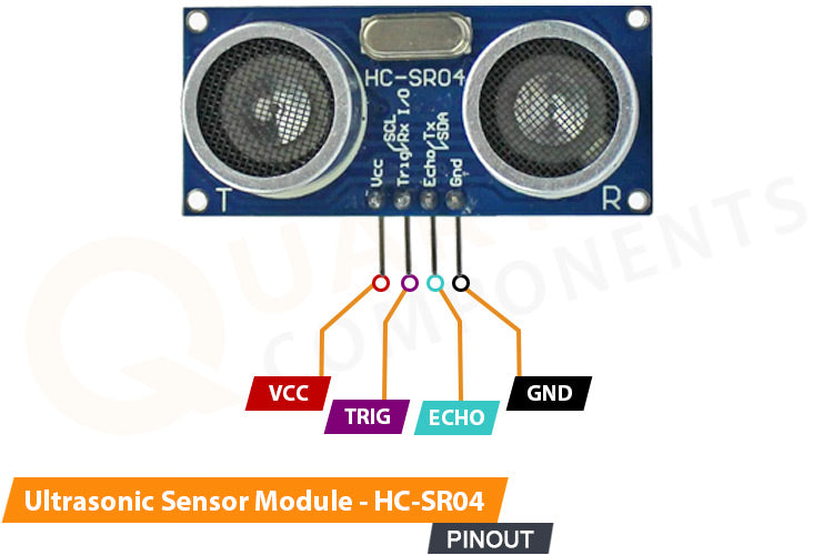
The Sensor has Four-pin terminals
- VCC (Voltage Supply): The pin provides power to the sensor which is 5 volts (5V).
- GND (Ground): This pin is used to connect the sensor to the ground (0V).
- Trig (Trigger): The trigger pin is used to initiate the distance measurement. When you send a short pulse (typically 10 microseconds) to this pin, the sensor will send out an ultrasonic sound wave. It acts as an Input pin for the Sensor.
- Echo: The pin senses the reflected ultrasonic sound wave. It outputs a pulse whose width is proportional to the time the sound wave takes to bounce back after hitting an object. It acts as an output pin for the sensor.
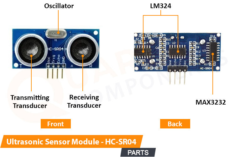
- Transmitting Transducer: The Transducer transmits eight sound waves pulses of 40khz frequency.
- Receiving Transducer: The Transducer senses the incoming sound pulses reflected by an object.
- Oscillator: It is used to oscillate the internal circuit at a particular frequency to generate the transmitting ultrasonic signals.
- LM324: The LM324 is a general-purpose quad operational amplifier (op-amp) IC that is used to amplify the received and transmitting signals. Also, it is used as a Comparator or filtering purposes to filter out unwanted frequency signals.
- MAX3232: The IC used to facilitate the serial communication or RS-232 signals (TX, RX, RTS, CTS, etc.) conversion to TTL/CMOS signals for microcontrollers or digital devices. Basically, a voltage-level conversion of serial data signals between RS-232 and TTL/CMOS levels.
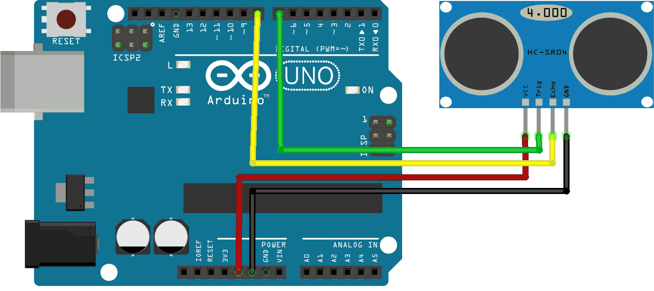
Circuit Diagram - Interfacing Ultrasonic Sensor with Arduino
Interesting projects can be created by interfacing ultrasonic sensors with a microcontroller like Arduino. We will interface it with Arduino and observe the Sensor's working mechanism, which is obviously the distance measurement.
Components Required:
The Sensor’s four pins have to connect with the Microcontroller
- The VCC pin should be connected with 5v whereas the GND to the Ground pin on the Arduino Board.
- Trig & Echo are digital interfacing pins that should be connected to any two digital pins on the Arduino.
Arduino Code to Interface Ultrasonic Sensor Module with Arduino Uno
The code triggers the Trig pin on the sensor to transmit the sound waves while observing the HIGH time of the Echo pin to calculate the distance measurement using the formula distance=duration*340/20000. The sensor displays the distance measurement data on a serial monitor
Demonstration of IR Proximity Sensor Module
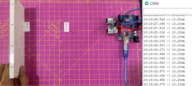
Power the Arduino after successful connection & and code setup. Open the Serial Monitor and select the correct Baud rate. Place an object at a certain distance, facing the ultrasonic sensor’s transducers.
Now, you can see the output, as the below Image shows the Ultrasonic output distance measurement on the serial monitor.
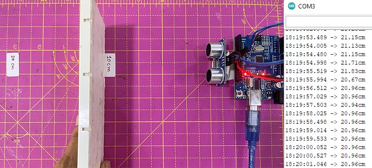
When we put an obstructed object 10cm away from the sensor, it will display the accurate results on the Serial monitor. Also, the below image shows the true readings of the sensor at 20cm.
Hope you liked and enjoyed the project and learned something valuable from it. If you have any questions, you can leave them in the comment section below.