


How to Interface TCS3200 Color Sensor with Arduino
The TCS3200 color sensor can detect the color of an object and generate a corresponding frequency signal in the form of a square wave. This sensor module comprises the TAOS TCS3200 RGB Sensor IC and is equipped with four white LEDs to illuminate the object, ensuring accurate color detection. The sensor chip features an 8x8 Photodiode array to precisely determine the object's color and produce a frequency signal corresponding to the detected color using a Current-to-frequency converter. It finds applications in tasks such as Ambient Light Sensing and Calibration, Color Matching, Printers, Robotics, and more. Moreover, it can serve as a suitable replacement option for the TCS230 Color Sensor.
TCS3200 Color Sensor Specifications
- Operating voltage: 7V to 5.5V
- Interface: Digital TTL
- High-resolution conversion of light intensity to frequency
- Programmable color and full-scale output frequency
- It can be directly connected to the digital pins of the Arduino
- Power down feature
- Working temperature: -40 C to 85 C
TCS3200 Color Sensor Working Principle
The TCS3200 color sensor works on the principle of color detection through the measurement of light intensity at specific wavelengths. When the internal LED is on, it illuminates the object or surface being examined with light. The color of the object reflects or absorbs specific wavelengths of light.
The photodiodes detect the light reflected from the object. Each photodiode is sensitive to a particular color due to its color filter. Then, the sensor modulates this information into PWM signals based on the absorbed color intensity. By analyzing these signals, you can determine the color of an object.
Pinout & Parts Description of TCS3200 Based Color Sensor
Generally, there are eight total pins found on the Sensor
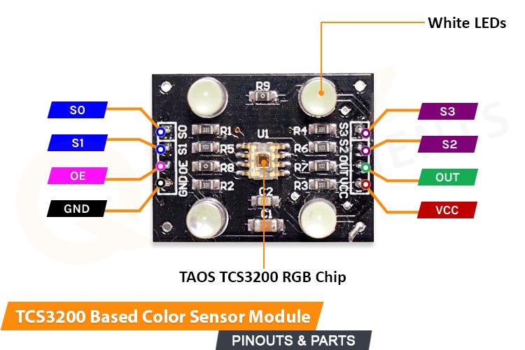
- VCC (Voltage Supply): The pin provides power to the sensor which can be 5 volts (5V).
- GND (Ground): This pin is used to connect the sensor to the ground (0V).
- S0 and S1: These pins are used to set the frequency scaling factor. By toggling these pins between high and low states, you can select from different frequency scales, which in turn affect the sensitivity of the sensor to different colors.
|
S0 S1 OUTPUT FREQUENCY SCALING(f0) L L Power down L H 2% H L 20% H H 100% |
- S2 and S3: These pins are used to select the type of color filtering applied by the sensor.
|
S2 S3 PHOTODIODE TYPE L L RED L H BLUE H L CLEAR (NO FILTER) H H GREEN |
- OE (Output Enable): Control the Sensor output pin. Making it LOW will enable the sensor output.
- OUT: Provides the PWM Signal Output.
Circuit Diagram - TCS3200 Color Sensor with Arduino

The sensor can be easily interfaced with Arduino using connection wires and all available components. We are incorporating 3 (Red, Blue, and green) led with Arduino to represent them as an indication of particular color detection.
Components Required:
- TCS3200 Color Sensor Module
- Arduino Uno R3
- LED 5mm – (Red, Green, Blue)
- Jumper wires
- VCC and GND pin of the sensor connects to 5v and Ground pin on Arduino. Also, OE should be connected to the Ground
- S0, S1, S2, S3, and OUT pins must be connected to any digital pins on Arduino.
- The LEDs common GND connect to the Ground of Arduino while the +ve terminal of each LED is connected to separate digital pins on board.

Arduino Code to interface TCS3200 Color Sensor
The code communicates with the sensor using S0, S1, S2, S3 and OUT pins. The output LEDs will quickly indicate the color that has been detected. We are fixing the frequency scaling at 20% hence we are putting the S0 & S1 as HIGH and LOW. Controlling S2 and S3 inside the loop will command the sensor to detect all RGB frequencies repeatedly. Using the PulseIn() function, we are getting the frequency value of an OUT pin.
The IF conditions filter the output frequency in such a mechanism to detect a particular color based on the frequency changes.
The sensor output frequency values can be affected by the Surrounding Light Intensity as well as the color object in front of it. However, it also depends on the scaling factor.
The color object must be a material that reflects some amount of white light toward the sensor.
The Calibration of the sensor is a little complicated but it can be done easily. Calibrate it in a constant surround light intensity by fixing it at a fixed position.
The code provides Serial monitor commands to calibrate values on the serial monitor. And made changes inside the code.
#define S0 6
#define S1 7
#define S2 8
#define S3 9
#define Out 10
int redLed = 11;
int greenLed = 12;
int blueLed = 13;
void setup() {
Serial.begin(9600); // Change the baud rate to 9600
pinMode(S0, OUTPUT);
pinMode(S1, OUTPUT);
pinMode(S2, OUTPUT);
pinMode(S3, OUTPUT);
pinMode(redLed, OUTPUT);
pinMode(greenLed, OUTPUT);
pinMode(blueLed, OUTPUT);
pinMode(Out, INPUT_PULLUP); // Use INPUT_PULLUP to enable the internal pull-up resistor on the input pin
digitalWrite(S0, HIGH);
digitalWrite(S1, LOW); // Setting frequency selection to 20%
}
void loop() {
digitalWrite(S2, LOW);
digitalWrite(S3, LOW); // Setting for RED color sensor
int redFrequency = pulseIn(Out, LOW); // Reading frequency
Serial.print("R: ");
Serial.print(redFrequency);
Serial.print(" ");
delay(500);
digitalWrite(S2, LOW);
digitalWrite(S3, HIGH); // Setting for BLUE color sensor
int blueFrequency = pulseIn(Out, LOW); // Reading frequency
Serial.print("B: ");
Serial.print(blueFrequency);
Serial.print(" ");
delay(500);
digitalWrite(S2, HIGH);
digitalWrite(S3, HIGH); // Setting for GREEN color sensor
int greenFrequency = pulseIn(Out, LOW); // Reading frequency
Serial.print("G: ");
Serial.print(greenFrequency);
//Serial.println();
if (redFrequency < blueFrequency && redFrequency < greenFrequency && redFrequency < 40) {
Serial.println(" - (Red Color)");
digitalWrite(redLed, HIGH); // Turn RED LED ON
digitalWrite(greenLed, LOW);
digitalWrite(blueLed, LOW);
}
else if (blueFrequency < redFrequency && blueFrequency < greenFrequency && blueFrequency < 50) {
Serial.println(" - (Blue Color)");
digitalWrite(redLed, LOW);
digitalWrite(greenLed, LOW);
digitalWrite(blueLed, HIGH); // Turn BLUE LED ON
}
else if (greenFrequency < redFrequency && greenFrequency < blueFrequency && greenFrequency < 85) {
Serial.println(" - (Green Color)");
digitalWrite(redLed, LOW);
digitalWrite(greenLed, HIGH); // Turn GREEN LED ON
digitalWrite(blueLed, LOW);
}
else {
Serial.println(" - (NO Colour)");
digitalWrite(redLed, LOW);
digitalWrite(greenLed, LOW);
digitalWrite(blueLed, LOW);
}
delay(500); // Add a delay before the next reading to reduce rapid changes
}
Demonstration of TCS3200 Color Sensor Module
Upload the code to Arduino, and correctly calibrate the sensor while not displacing it. Make calibration changes inside the code and test properly 2-3 times.
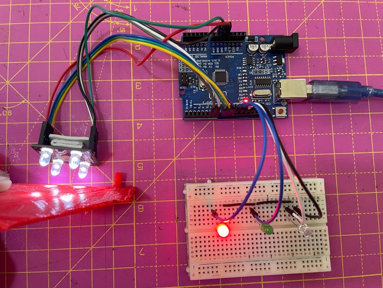
Now, your color-sensing device is Ready as you can see in the below image. When we put a red reflecting object in front of the sensor, the red LED is glowing.
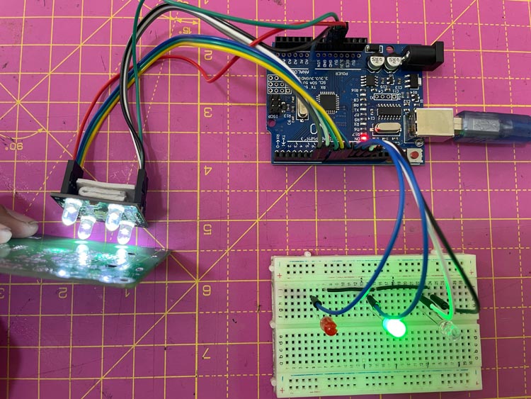
Now, if we put the green object, you can see that the green LED is glowing as in the image below
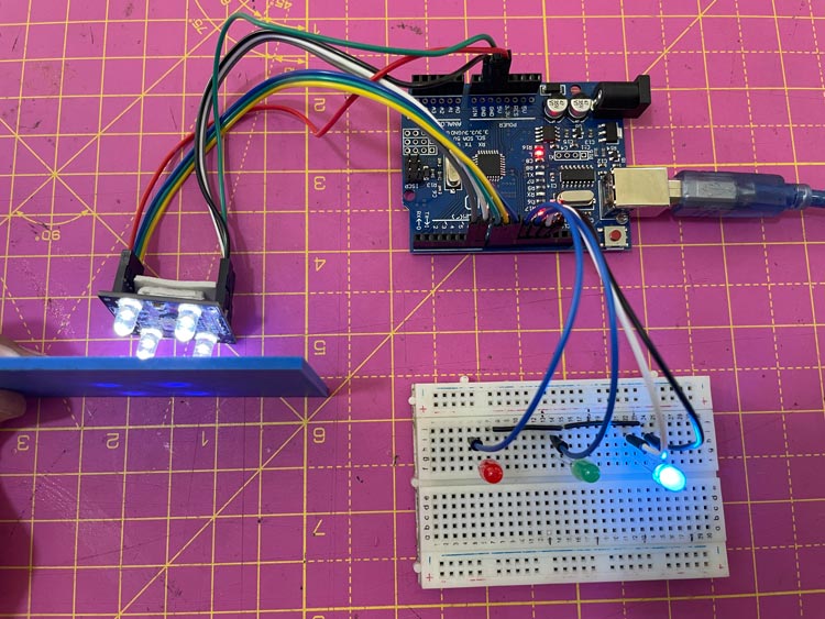
And similarly, the blue object makes your Blue Led to turn on.
I hope you liked and enjoyed the project and learned something valuable from it. If you have any questions, you can leave them in the comment section below.