


How to Interface 20x4 Graphical LCD Display with Arduino
LCD Display modules are commonly used in most of the embedded projects to display various output data. It's cheap, handy, and programmer-friendly for various DIY projects. The Alphanumeric Graphical LCD (2004A) is a 20x4 Liquid Crystal Display that comes in blue or green colors. It can show four lines of text, with each line holding up to 20 characters making a total of 80 characters to be displayed on screen. This is larger than the 16x2 LCD, but the programming is similar. The display is used to show a wide range of things like text, characters, numbers, and symbols.
20x4 Graphical LCD Display Specifications
- Operating Supply voltage: 5 volts
- Backlight Operating Voltage: 5 volts
- Uses the industry-standard HD44780 LCD controller
- Supports both 4-bit and 8-bit parallel interfaces
- Working Temperature: -20°C to 70°C
- Character Size: 5x8 pixels dot matrix
20x4 LCD Display Module Pinout
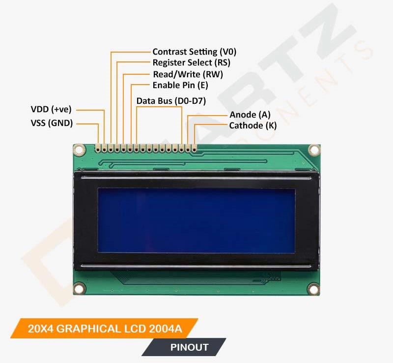
The typical pinout for a 20x4 LCD is:
- VSS (Ground): The pin connects to the ground (0V) of the supply.
- VDD (Power Supply): Pin used to provide +5v power supply to the module.
- VO (Contrast Control): Connect to a potentiometer to control the contrast of the display. Adjusting the voltage at this pin will change the contrast.
- RS (Register Select): Used to select between data (RS=1) and command (RS=0) modes.
- RW (Read/Write): Typically connected to ground (RW=0) to set the LCD in write mode.
- E (Enable): Enables the LCD to latch data present on the data bus when transitioning from high to low.
- D0-D7 (Data Bus): These are the data lines. You can use either 4-bit mode (D4-D7) or 8-bit mode (D0-D7) depending on your setup. In 4-bit mode, you only need to connect D4-D7.
- LED+ (Backlight Anode): Connect to the positive side of the backlight LED or resistor for current control.
- LED- (Backlight Cathode): Connect to the negative side of the backlight LED.
Circuit Diagram for Interfacing 20x4 LCD with Arduino
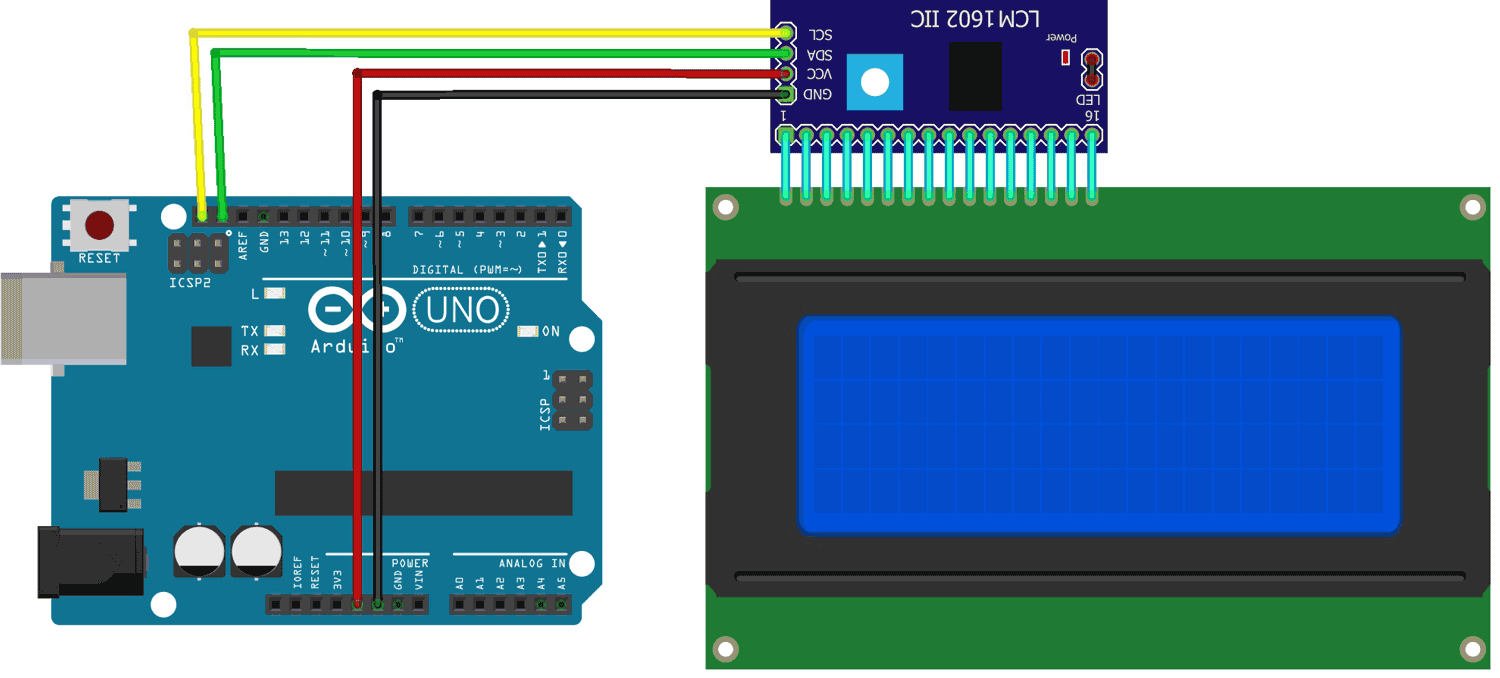
The LCD can also be interfaced with Arduino using I2C communication protocol, it is simple and beginners friendly and doesn’t require too much wiring. For that, an I2C Serial Adaptor module is Required.
Components Required:
The interfacing of the I2C-serial backpack module with LCD makes the whole connection & programming easy.
Simply connect all 16 pins on the I2C adaptor to Display as shown in the connection diagram. The I2C adaptor module has an inbuilt potentiometer to adjust the backlight of the display module.
The Arduino connection of the I2C adaptor includes Four wires named: VCC, GND, SDA, and SCL.
The VCC and GND connect to the respective 5-volt pin and ground pin of the Arduino whereas the SDA & SCL connect to pin SDA and SCL pins on the Arduino. Both SDA & SCL indicate the I2C communication with Arduino.
Arduino Code for Interfacing 20x4 Graphical LCD with Arduino
The code communicates with the display to print some text on it. For I2C communication, we are using a library LiquidCrystal_I2C.h which is used to handle all I2C communication as well as the Display functions that we have used in our code.
Demonstration of 20x4 Graphical LCD with Arduino
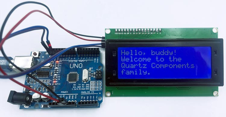
In our code, we aim to display text on the LCD. After you've successfully connected and uploaded the code, you'll notice that the text appears clearly on your LCD. However, if the text appears jumbled or incorrect due to text changes made inside the code, you can resolve this by adjusting the values within the setCursor() function. This is how you can ensure that your display functions properly and looks appealing.
Hope you liked and enjoyed the project and learned something valuable from it. If you have any questions, you can leave them in the comment section below.