


Free Shipping
Free standard shipping on all orders over INR 500

COD Available
On all the orders above INR 500

Free Returns
*Terms & Conditions Applied

Customer Assistance
Contact Us :
0141-4946677 or support@quartzcomponents.com

16x2 LCD Display (Green Backlight)
SKU:
MOD-QC0139
Availability:
1308
In Stock
-
- Rs. 112.00
- Unit price
- per
Subtotal:
Rs. 112.00
Description
xThe 16x2 Alphanumeric LCD Display Module is equally popular among hobbyists and professionals for its affordable price and easy to use nature. As the name suggests the 16x2 Alphanumeric LCD can show 16 Columns and 2 Rows therefore a total of (16x2) 32 characters can be displayed. Each character can either be an alphabet or number or even a custom character. This particular LCD gas a green backlight, you can also get a Blue Backlight LCD to make your projects stand our and visually appealing, apart from the backlight color both the LCD have the same specifications hence they can share the same circuit and code. If your projects require more characters to be displayed you can check the 20x4 Graphical LCD which has 20 Columns and 4 Rows and hence can display up to 80 characters.
Specifications of 16x2 LCD Display Module:
- Operating Voltage: 4.7V to 5.3V
- Operating Current 1mA (without backlight)
- Can display (16x2) 32 Alphanumeric Characters
- Custom Characters Support
- Works in both 8-bit and 4-bit Mode
The 16x2 LCD pinout diagram is shown below. As you can see the module has (from right) two power pins Vss and Vcc to power the LCD. Typically Vss should be connected to ground and Vcc to 5V, but the LCD can also operate from voltage between 4.7V to 5.3V. Next, we have the control pins namely Contrast (VEE), Register Select (RS), Read/Write (R/W) and Enable (E). The Contrast pin is used to set the contrast (visibility) of the characters, normally it is connected to a 10k potentiometer so that the contrast can be adjusted. The Read/Write pin will be grounded in most cases because we will only be writing characters to the LCD and not read anything from it. The Register Select (RS) and Enable pin (E) pin are the control pins of the LCD and will be connected to the digital pins GPIO pins of the microcontroller. These pins are used to instruct the LCD where place a character when to clear it etc.

From DB0 to DB7 we have our eight Data Pins which are used to send information about the characters that have to be displayed on the LCD. The LCD can operate in two different modes, in the 4-bit Mode only pins DB4 to DB7 will be used and the pins DB0 to DB3 will be left idle. In 8-bit Mode, all the eight-pin DB0 to DB7 will be used. Most commonly the 4-bit mode is preferred since it uses only 4 Data pins and thus reduces complexity and GPIO pin requirement on the microcontroller. Finally, we have the LED+ and LED- pins which are used to power the backlight LED inside our Display module. Normally the LED+ pin is connected to 5V power through a 100 ohm current limiting resistor and the LED- pin is connected to Ground.
Pin Description of 16x2 LCD Display:
|
Pin No. |
Pin Symbol |
Pin Name |
Connection Description |
|
1 |
VSS |
Ground |
Connected to Ground |
|
2 |
VCC |
Power |
Connected to Power (Typically 5V) |
|
3 |
VEE |
Contrast |
Connected to potentiometer 10k to control contrast |
|
4 |
RS |
Register Select |
Connected to Microcontroller |
|
5 |
R/W |
Read/Write |
Connected to Ground |
|
6 |
E |
Enable |
Connected to Microcontroller |
|
7 |
DB0 |
Data Pin 0 |
Connected to Microcontroller based on 4-bit or 8-bit Working Mode |
|
8 |
DB1 |
Data Pin 1 |
|
|
9 |
DB2 |
Data Pin 2 |
|
|
10 |
DB3 |
Data Pin 3 |
|
|
11 |
DB4 |
Data Pin 4 |
|
|
12 |
DB5 |
Data Pin 5 |
|
|
13 |
DB6 |
Data Pin 6 |
|
|
14 |
DB7 |
Data Pin 7 |
|
|
15 |
LED+ |
LED Positive |
Connected to 5V through 100 ohm Resistor |
|
16 |
LED- |
LED Negative |
Connected to Ground |
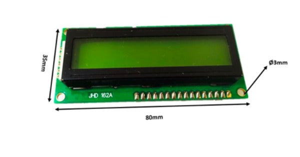
The dimensions of 16x2 LCD display is shown below
Shipping & Return
xReturns Policy
Due to the type of products we sell, we accept limited returns. Below are the conditions where we can accept a return request.
1. Damaged During Shipment
You must report any damage within 3 days of receiving the product. Please send clear pictures of the damaged item and packaging along with a short description. Once our support team accepts the claim, we will arrange a replacement or a full refund, including return shipping costs.
2. Wrong Item Shipped
If the item you received is different from what is shown on our website, you must report it within 3 days of receiving the product. Please send a video of the first-time unboxing that clearly shows the sealed package, the opening process, and the products received, along with clear pictures and a short description of the issue. Once our support team verifies the claim, we will accept the return and provide a refund or replacement as per your choice.
3. Defective Items
If the product is defective or not functioning as described, please notify us within 3 days of receiving the product. Include proper pictures, a short video, and a description of the issue. Once our support team verifies the defect, we will provide a replacement or a complete refund, including the return shipping cost.
4. Missing Items
If any item or accessory listed on the order is missing from the package, you must notify us within 3 days of receiving the product. You are required to record a proper video while unboxing the package for the first time (showing the sealed package, opening process, and all contents). Please also share pictures of the received items and the packing list or invoice. Once our support team confirms the missing item, we will ship the missing item at no extra cost or issue a partial refund.
Limitation of Returns
We don’t accept returns for products damaged due to improper use. Moreover, we don’t accept returns if the ordered product is not suitable for a specific application. Please read the product specifications and datasheet carefully before placing an order. Returns are accepted only within 3 days from the date of delivery.
Shipping
We ship all over India with free shipping on all prepaid orders above ₹500. For Cash on Delivery (COD) orders, ₹80 will be charged for orders below ₹599 and ₹30 for orders above ₹599.
For any questions related to shipping, please contact our support team at support@quartzcomponents.com.
Note: The minimum order value for COD orders is ₹500.
Related Products
Q
Example product title
-
- Rs. 112.00
- Unit price
- per
Q
Example product title
-
- Rs. 112.00
- Unit price
- per
Q
Example product title
-
- Rs. 112.00
- Unit price
- per
Q
Example product title
-
- Rs. 112.00
- Unit price
- per
Q
Example product title
-
- Rs. 112.00
- Unit price
- per
Q
Example product title
-
- Rs. 112.00
- Unit price
- per
Q
Example product title
-
- Rs. 112.00
- Unit price
- per
Q
Example product title
-
- Rs. 112.00
- Unit price
- per
Q
Example product title
-
- Rs. 112.00
- Unit price
- per
Q
Example product title
-
- Rs. 112.00
- Unit price
- per
- Choosing a selection results in a full page refresh.