


Building a DIY RC Car with Arduino Uno, Joystick, NRF24L01, and L298N
Hey there! Remote-controlled (RC) cars have been a source of fascination for hobbyists and enthusiasts of all ages. Are you ready to dive into the exciting world of robotics and remote-controlled (RC) cars? Imagine having your very own car that you can control wirelessly and maneuver around obstacles that provide endless hours of entertainment. In this blog post, we're going to show you how to build your own DIY RC car using commonly available components like Arduino Uno, a joystick module, NRF24L01 wireless module, and an L298N motor driver. Previously, we have built line-following robot, surveillance robot car, or obstacle-avoiding robot, you can check out.
So, gear up and get ready to embark on a thrilling journey into the world of DIY robotics!
Components Required
- Arduino Uno
- Analog Joystick module
- NRF24L01 wireless module
- L298N motor driver
- RC car chassis
- DC motors
- Battery pack
- Jumper wires
- Breadboard (optional)
- Screwdriver and screws
What is the NRF24L01 module?
The NRF24L01 is a wireless communication module that allows devices to communicate with each other without the need for physical wires. It operates on the 2.4 GHz frequency and is commonly used in DIY projects for remote control, data transmission, and sensor networks. It provides a low-cost and reliable solution for short-range wireless communication, making it popular among hobbyists and Arduino enthusiasts. With the NRF24L01, you can establish wireless connections between devices and enable them to exchange data and control signals over short distances.
It operates in 3 modes:
- In transmitting mode, when the power is 0dBm, then the NRF24L01 uses only 11.3mA current.
- While in receiving mode, it uses only 13.5mA current.
- In the transceiver mode, the NRF24L01 module is used for long-distance and quick transmission of data using the SPI protocol.
The technical specifications include a frequency range of 2.4 GHz in the ISM band, a maximum air data rate of 2 Mb/s, GFSK modulation format, a maximum output power of 0 dBm, operating supply voltage ranging from 1.9 V to 3.6 V, maximum operating current of 13.5 mA, minimum current of 26 µA in standby mode, logic inputs that are 5V tolerant, and a communication range of 800+ meters in line of sight.
NRF24L01 Pinout:
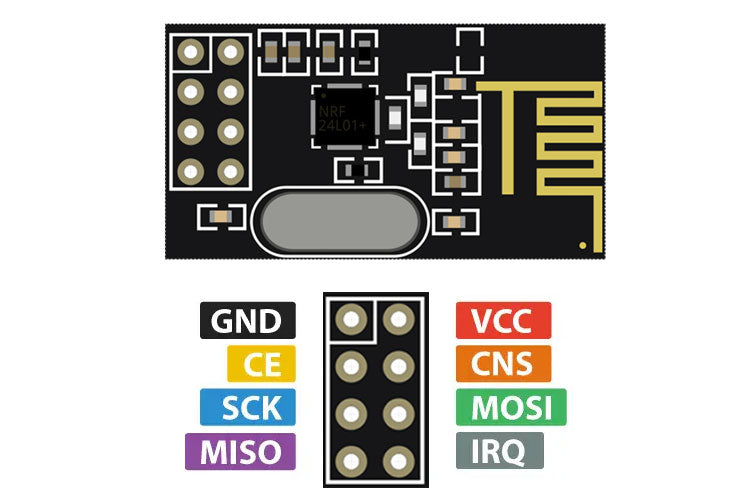
- VCC: This pin is used to provide the power supply voltage for the module. It usually operates at 3.3V, but some modules may support a wider voltage range.
- GND: This pin is the ground reference for the module and should be connected to the ground of the power supply.
- CE (Chip Enable): This pin is used to enable or disable the operation of the nRF24L01. It is an active-high pin, meaning the module is active and ready to transmit or receive data when this pin is set to high. When this pin is set to low, the module is in standby or power-saving mode.
- CSN (Chip Select Not): This pin is used for the SPI (Serial Peripheral Interface) communication. It is used to select the nRF24L01 during data transfer. When the CSN pin is pulled low, the module is selected, and data can be sent or received over the SPI bus.
- SCK (Serial Clock): This pin is the SPI clock input. It is used to synchronize the data transfer between the microcontroller and the nRF24L01.
- MOSI (Master Out Slave In): This pin is used for SPI communication. It carries data from the microcontroller to the nRF24L01 during data transfer.
- MISO (Master In Slave Out): This pin is used for SPI communication. It carries data from the nRF24L01 to the microcontroller during data transfer.
- IRQ: This pin is the interrupt request pin. It can be used to generate an interrupt signal to the microcontroller when certain events occur, such as the reception of a new packet or the completion of data transmission. The specific events that trigger the interrupt can be configured through the module's registers.
What is an Analog Joystick?
An analog joystick is a type of input device commonly used in gaming consoles, remote control systems, and other applications where precise control over movement is required. It consists of a movable stick that can be tilted or pushed in different directions, allowing users to control the position or movement of a cursor, character, or object in a game or application.
Analog Joystick Pinout:

- VCC: This pin is used to provide the power supply voltage to the joystick.
- GND: This pin is the ground reference for the joystick and should be connected to the ground of the power supply.
- X-axis: This pin represents the analog output for the horizontal movement of the joystick. It provides a variable voltage or current signal that corresponds to the position of the joystick along the X-axis. The voltage or current level changes as the joystick is moved left or right.
- Y-axis: This pin represents the analog output for the vertical movement of the joystick. Similar to the X-axis pin, it provides a variable voltage or current signal that corresponds to the position of the joystick along the Y-axis. The voltage or current level changes as the joystick is moved up or down.
- Button(s): Some analog joysticks also feature one or more push buttons integrated into the joystick housing. These buttons are typically connected to separate pins. When a button is pressed, the corresponding pin will either be pulled low or generate a logic signal indicating a button press event.
What is L298N Motor Driver?
The L298N is a popular dual H-bridge motor driver integrated circuit (IC) commonly used to control and drive DC motors, stepper motors, and other types of motors. It provides bidirectional control of motors, allowing them to rotate in both forward and reverse directions.
L298N Pinout:

- ENA (Enable A) - This pin is used to enable or disable the output driver for motor channel A. By providing a PWM (Pulse Width Modulation) signal to this pin, the speed of the motor connected to channel A can be controlled. If this pin is held low, the motor will be disabled.
- IN1 (Input 1) - This pin is one of the input pins for motor channel A. It is used to control the direction of rotation for motor channel A. By setting the logic level on this pin, the motor can be made to rotate forward or reverse.
- IN2 (Input 2) - This pin is the second input pin for motor channel A. Like IN1, it is used to control the direction of rotation for motor channel A. The combination of logic levels on IN1 and IN2 determines the motor's direction.
- IN3 (Input 3) - This pin is one of the input pins for motor channel B. It works similarly to IN1 but controls the direction of rotation for motor channel B.
- IN4 (Input 4) - This pin is the second input pin for motor channel B. It functions similarly to IN2 but controls the direction of rotation for motor channel B.
- ENB (Enable B) - This pin is used to enable or disable the output driver for motor channel B. By providing a PWM signal to this pin, the speed of the motor connected to channel B can be controlled. If this pin is held low, the motor will be disabled.
- OUT1: Output 1) - This pin is one of the output pins for motor channel A. It provides the voltage supply for the motor connected to channel A in one direction of rotation.
- OUT2 (Output 2) - This pin is the second output pin for motor channel A. It provides the voltage supply for the motor connected to channel A in the opposite direction of rotation.
- OUT3: Output 3 - This pin is one of the output pins for motor channel B. It provides the voltage supply for the motor connected to channel B in one direction of rotation.
- OUT4 (Output 4) - This pin is the second output pin for motor channel B. It provides the voltage supply for the motor connected to channel B in the opposite direction of rotation.
- VCC: This pin is used to provide the power supply voltage (usually +5V) for the internal circuitry of the L298N.
- GND: This pin is the ground reference for the motor driver and should be connected to the ground of the power supply.
- Vs: This pin is used to provide the main power supply voltage for the motors. It typically requires a higher voltage (e.g., +12V to +35V) to drive the motors.
- Sense A: This pin is used to provide a feedback signal from motor channel A. It can be used to monitor the current flowing through the motor for overcurrent protection or other purposes.
- Sense B: This pin is similar to Sense A but provides a feedback signal from motor channel B.
Working and Circuit Diagram of RC Car
- Transmitter Side:

- The analog joystick on the transmitter side acts as the control input. As you move the joystick in different directions, it generates analog voltage values on its X-axis and Y-axis pins.
- The Arduino Uno reads these analog values using its analog input pins. The values indicate the position of the joystick along the X and Y axes, representing the desired direction of movement.
- The Arduino maps these analog values to appropriate motor speed and direction values based on predefined ranges. For example, if the joystick is moved forward, the Arduino may set a positive motor speed value for both motors.
- The Arduino uses the nRF24L01 wireless module to transmit the motor speed and direction data wirelessly to the receiver Arduino.
- The nRF24L01 module encodes the data into packets and sends them over the air using the configured channel and address.
- Receiver Side:

- The nRF24L01 module on the receiver side receives the data packets transmitted by the transmitter Arduino.
- The Arduino Uno on the receiver side reads and decodes the received data packets from the nRF24L01 module.
- The Arduino extracts the motor speed and direction values from the received data packets.
- Based on the received values, the Arduino controls the motors connected to the L298N motor driver.
- The Arduino sets the appropriate logic levels on the IN1, IN2, IN3, and IN4 pins of the L298N motor driver to control the motor rotation and direction. For example, it might set IN1 and IN3 to HIGH and IN2 and IN4 to LOW for forward motion.
- The Arduino can also adjust the speed of the motors by setting the appropriate PWM values on the ENA and ENB pins of the L298N motor driver.
- Motor Control:
- The L298N motor driver receives the control signals from the Arduino and drives the connected motors accordingly.
- The motor driver interprets the logic levels on the IN1, IN2, IN3, and IN4 pins to determine the motor rotation and direction.
- By adjusting the logic levels, the motor driver can make the motors rotate forward, reverse, or stop based on the desired movement determined by the Arduino.
- The PWM signals on the ENA and ENB pins control the speed of the motors. The motor driver adjusts the supplied voltage to the motors based on the PWM duty cycle, controlling their speed.

Code for Transmitter (Remote Control)
#include <SPI.h>
#include <nRF24L01.h>
#include <RF24.h>
RF24 radio(9, 8); // CE, CSN
const byte address[6] = "00001";
void setup() {
radio.begin();
Serial.begin(115200);
radio.openWritingPipe(address);
}
void loop() {
// Read joystick values
int xValue = analogRead(A0);
int yValue = analogRead(A1);
// Determine the joystick position
String position;
if (yValue < 400) {
position = "Forward";
} else if (yValue > 600) {
position = "Backward";
} else if (xValue < 400) {
position = "Left";
} else if (xValue > 600) {
position = "Right";
} else {
position = "Neutral";
}
// Send the joystick position data to the receiver
radio.write(position.c_str(), position.length() + 1);
delay(10);
}
Code for Receiver (RC Car)
#include <SPI.h>
#include <nRF24L01.h>
#include <RF24.h>
RF24 radio(9, 8); // CE, CSN
const byte address[6] = "00001";
// Motor pins
const int in1Pin = 4;
const int in2Pin = 5;
const int in3Pin = 6;
const int in4Pin = 7;
void setup() {
radio.begin();
Serial.begin(115200);
radio.openReadingPipe(1, address);
radio.startListening();
// Set motor pins as outputs
pinMode(in1Pin, OUTPUT);
pinMode(in2Pin, OUTPUT);
pinMode(in3Pin, OUTPUT);
pinMode(in4Pin, OUTPUT);
}
void loop()
{
if (radio.available())
{
char position[10];
radio.read(&position, sizeof(position));
Serial.println(position);
// Perform action based on the received position
if (position == "Forward") {
moveForward();
} else if (position == "Backward") {
moveBackward();
} else if (position == "Left") {
turnLeft();
} else if (position == "Right") {
turnRight();
} else {
stopMotors();
}
}
}
// Move the car forward
void moveForward() {
digitalWrite(in1Pin, HIGH);
digitalWrite(in2Pin, LOW);
digitalWrite(in3Pin, HIGH);
digitalWrite(in4Pin, LOW);
}
// Move the car backward
void moveBackward() {
digitalWrite(in1Pin, LOW);
digitalWrite(in2Pin, HIGH);
digitalWrite(in3Pin, LOW);
digitalWrite(in4Pin, HIGH);
}
// Turn the car left
void turnLeft() {
digitalWrite(in1Pin, LOW);
digitalWrite(in2Pin, HIGH);
digitalWrite(in3Pin, HIGH);
digitalWrite(in4Pin, LOW);
}
// Turn the car right
void turnRight() {
digitalWrite(in1Pin, HIGH);
digitalWrite(in2Pin, LOW);
digitalWrite(in3Pin, LOW);
digitalWrite(in4Pin, HIGH);
}
// Stop the motors
void stopMotors() {
digitalWrite(in1Pin, LOW);
digitalWrite(in2Pin, LOW);
digitalWrite(in3Pin, LOW);
digitalWrite(in4Pin, LOW);
}