


Accurate timekeeping is crucial in various applications, from simple household clocks to complex time-tracking systems in industries. In this project, we will build a digital clock using an Arduino microcontroller, a DS3231 real-time clock (RTC) module, and a 16x2 LCD display. This project is practical for a wide range of applications where reliable and precise timekeeping is needed. It is also an excellent way to understand the basics of RTC operation and interfacing with microcontrollers like Arduino.
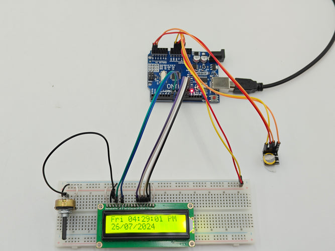
In this project, we will cover the basic concept of interfacing an RTC module with an Arduino, setting up the time, and displaying the current date and time on an LCD. Below, you can see a working setup of our project, which we will be building in this project.
Components Required
About the DS3231 Module
The DS3231 RTC module is a highly accurate timekeeping device that integrates a temperature-compensated crystal oscillator to maintain consistent timing even in fluctuating temperature environments. Its high accuracy is within ±2 minutes per year, making it ideal for applications requiring precise timekeeping. The module also features an integrated battery backup, allowing it to continue keeping time when the main power supply is lost. This ensures that the time remains accurate and up-to-date without requiring manual resetting after power interruptions. The DS3231 module communicates with the Arduino via the I2C protocol, making it easy to interface and program for a variety of time-sensitive applications.

Pinout Explanation
Your DS3231 RTC module has five pins, which simplifies the connections needed for basic operation. Here’s a breakdown of each pin:
-
+ (VCC): This pin powers the DS3231 module. It typically requires a voltage supply of 3.3V or 5V, depending on the module's specifications.
-
G or - (GND): The ground pin should be connected to the ground pin on the Arduino. It provides the necessary ground reference for the module to operate correctly.
-
NC (Not Connected): This pin is not connected to any circuitry within the module and can be ignored. It's often included in the pinout for mechanical stability.
-
C (SCL): This is the clock line for the I2C communication protocol. It should be connected to the SCL pin on the Arduino.
-
D (SDA): This is the data line for the I2C communication protocol. It should be connected to the SDA pin on the Arduino.
Digital Clock Circuit Diagram

Schematic Diagram

Connections
1. Connect the DS3231 RTC Module to Arduino:- VCC (+): Connect to 5V or 3.3V on the Arduino.
- GND (-): Connect to GND on the Arduino.
- C (SCL): Connect to the SCL pin on the Arduino. On an Arduino Uno, this is A5. On newer boards like the Arduino Mega, it is labeled SCL.
- D (SDA): Connect to the SDA pin on the Arduino. On an Arduino Uno, this is A4. On newer boards like the Arduino Mega, it is labeled SDA.
- NC (Not Connected): This pin is not used and can be left unconnected.
- VSS (Pin 1): Connect to GND on Arduino.
- VDD (Pin 2): Connect to 5V on Arduino.
- V0 (Pin 3): Connect to the wiper (middle pin) of a 10kΩ potentiometer.
- RS (Pin 4): Connect to digital pin 7 on Arduino.
- RW (Pin 5): Connect to GND on Arduino.
- E (Pin 6): Connect to digital pin 8 on Arduino.
- D4 (Pin 11): Connect to digital pin 9 on Arduino.
- D5 (Pin 12): Connect to digital pin 10 on Arduino.
- D6 (Pin 13): Connect to digital pin 11 on Arduino.
- D7 (Pin 14): Connect to digital pin 12 on Arduino.
- BLA (Pin 15): Connect to 5V through Arduino.
- BLK (Pin 16): Connect to GND on Arduino.
3. Potentiometer Connections:
- Pin 1: Connect to 5V on Arduino.
- Pin 2 (wiper): Connect to V0 (Pin 3) of the LCD.
- Pin 3: Connect to GND on Arduino.
Digital Clock with DS3231 RTC Module and LCD Display - Code Explanation
In this project, we use the Arduino IDE to create a digital clock utilizing the DS3231 Real-Time Clock (RTC) module and a LiquidCrystal display (LCD). The objective of this code is to initialize the RTC module, display the current time and date on the LCD, and ensure the clock updates every second.
First, we include the necessary libraries for interfacing with the RTC module and controlling the LCD. The Wire.h library is used for I2C communication, RTClib.h handles interactions with the DS3231 RTC module, and LiquidCrystal.h is used to control the 16x2 LCD display. These libraries provide essential functions to manage the hardware components.
#include <Wire.h>
#include <RTClib.h>
#include <LiquidCrystal.h>
Next, we declare instances for the RTC and LCD objects. The RTC_DS3231 class creates an object rtc to interface with the DS3231 module. Similarly, the LiquidCrystal class initializes an object lcd with the specified pin configuration (RS, E, D4, D5, D6, D7) for the LCD.
RTC_DS3231 rtc;
LiquidCrystal lcd(7, 8, 9, 10, 11, 12); // Pins: RS, E, D4, D5, D6, D7
In the setup function, we initialize the LCD with 16 columns and 2 rows. The code then checks if the RTC module is connected properly using rtc.begin(). If the RTC module is not found, an error message is displayed on the LCD, and the program halts. If the RTC module has lost power, it is adjusted using the date and time of the code compilation (DateTime(F(__DATE__), F(__TIME__))), which sets the correct time. A message indicating that the RTC and LCD are operational is shown before clearing the screen for the next display update.
void setup() {
lcd.begin(16, 2); // Initialize the LCD with 16 columns and 2 rows
if (!rtc.begin()) {
lcd.print("RTC Error");
while (1); // Halt if RTC is not found
}
if (rtc.lostPower()) {
lcd.clear();
lcd.print("RTC lost power");
delay(2000);
rtc.adjust(DateTime(F(__DATE__), F(__TIME__)));
}
lcd.clear();
lcd.print("RTC & LCD OK");
delay(2000);
lcd.clear();
}
In the loop function, we continuously fetch the current date and time from the RTC using rtc.now(). The LCD is cleared to update the displayed information. The first line of the LCD shows the day of the week and the current time in 12-hour format, including AM/PM indicators. The time is formatted with leading zeros where necessary. On the second line, the current date is displayed in the format DD/MM/YYYY, with leading zeros for single-digit days and months. The display updates every second to ensure the time is current.
DateTime now = rtc.now();
lcd.clear(); // Clear the LCD screen
// Display the day of the week and time on the first line
lcd.setCursor(0, 0); // Set cursor to column 0, row 0
lcd.print(dayNames[now.dayOfTheWeek()]); // Day of the week
lcd.print(' ');
// Display the time in 12-hour format
int hour = now.hour() % 12;
if (hour == 0) hour = 12; // Adjust for 12-hour format
if (hour < 10) lcd.print('0'); // Add leading zero for hour if necessary
lcd.print(hour, DEC);
lcd.print(':');
if (now.minute() < 10) lcd.print('0'); // Add leading zero for minute if necessary
lcd.print(now.minute(), DEC);
lcd.print(':');
if (now.second() < 10) lcd.print('0'); // Add leading zero for second if necessary
lcd.print(now.second(), DEC);
lcd.print(now.hour() < 12 ? " AM" : " PM"); // Display AM/PM
// Display the date on the second line
lcd.setCursor(0, 1); // Set cursor to column 0, row 1
if (now.day() < 10) lcd.print('0'); // Add leading zero for day if necessary
lcd.print(now.day(), DEC);
lcd.print('/');
if (now.month() < 10) lcd.print('0'); // Add leading zero for month if necessary
lcd.print(now.month(), DEC);
delay(1000); // Update every second
}